How Tethering System Design Affects Cap Mold Modification Requirements for Existing Injection Molds
How Tethering System Design Affects Cap Mold Modification Requirements for Existing Injection Molds
The European Union’s Single-Use Plastics Directive established a hard deadline: since July 2024, plastic caps on single-use beverage containers up to three liters must remain attached to the container throughout the product’s intended use stage [citation:14]. For cap molders with installed high-cavitation tooling, this created an immediate engineering problem. The tether is not an add-on feature. It requires geometric changes that ripple through the mold stack, from the neck ring to the slider mechanism to the hot runner gate position.
At cap-molds, we specialize in modifying existing injection molds for tethered closure production. This article examines how the specific tethering system design—whether hinge-based, strap-based, or double-cut—determines what actually needs to change in an existing mold, and which modification pathways preserve the largest portion of the original tooling investment.
Why Tethering Forces Mold Modification: The Geometric Reality
A conventional tamper-evident closure mold produces a cap with a continuous frangible bridge connecting the cap body to the tamper-evident band. When the consumer opens the bottle, that bridge breaks. The cap separates from the band, and the band remains on the bottle neck.
A tethered closure preserves that connection. The frangible bridge is replaced or supplemented by a tether structure—a strap, a hinge, or a retained bridge—that survives the opening action and continues to connect cap to container. Industry analysis of this transition is direct: “The tether requires more space in the area of the tamper evidence band. Hence, the screw caps had to be redesigned” [citation:5].
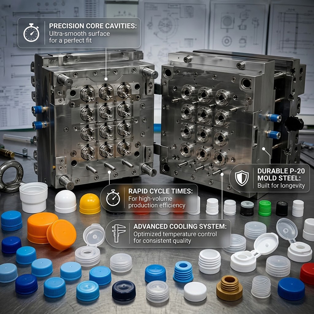
That “more space” translates into concrete mold modifications. The parting line for the slider mechanism must move upward to accommodate the tether geometry. The cavity insert must be re-machined to form the tether hinge or strap. The core cooling must be rebalanced because the tether area adds local mass that cools differently from the surrounding thin-wall sections [citation:13].
How Tethering System Design Dictates Modification Scope
Not all tethering systems impose the same tooling burden. The design approach determines whether an existing mold can be retrofitted with moderate changes or requires fundamental rebuilding.
Double-Cut Tethering: Minimal Tooling Impact
One tethering approach uses a double cut in the tamper-evident band to create a retained connection without adding hinge elements or torsion structures. The cap can be opened in stages, and the tethering is achieved purely through the slitting pattern [citation:9].
For existing molds, this approach is attractive because the cavity and core geometry can remain substantially unchanged. The modification focuses on the slitting station downstream of the molding process. A shorter blade that does not cut the full 360 degrees leaves one bridge intact, forming the tether [citation:12].
This is the lowest-impact modification pathway. The mold itself may require only minor adjustments to the stripper plate or ejection sequence. However, the resulting tether performance depends on the bridge geometry and the polymer’s mechanical properties at the hinge point.
Hinge-Based Tethering: Slide Height and Parting Line Changes
Hinge-based tethering designs—where the cap body connects to the retaining ring through one or more film hinges—impose more significant tooling changes. These designs typically require a higher parting line for the slider mechanism because the hinge geometry extends further up the cap skirt [citation:13].
The z-slides technology used in many high-cavitation cap molds provides a modular framework for this modification. The sliders must be made higher to accommodate the new parting line location. By changing the angles on the demolding face and increasing the height to approximately 15 mm, a standard cap mold can be converted to produce tethered closures [citation:13].
The critical constraint is cavity pitch. If the slide height increase pushes the mechanism into the space between cavities, the entire pitch would need to change—effectively requiring a new mold base. Modular slide systems that maintain the original pitch while accommodating taller sliders are therefore essential for retrofit viability [citation:13].
Strap-Based Tethering: Neck Ring and Cavity Insert Replacement
Strap-based tethering systems use one or more flexible strands or tabs connecting the cap to the retaining band. Berry Bramlage’s Lasso and V-Tethered designs, for example, place the closure beneath the neck or adjacent to it at a wide angle [citation:5].
These designs require the most extensive mold modification because the strap geometry must be formed in the cavity insert and the retaining band contour changes. The neck ring—the mold component that forms the thread and tamper band geometry—typically requires complete replacement [citation:6]. MHT’s analysis of the tethered cap transition notes that “in most cases tethered caps will involve new neck geometries for the preform. There simply has to be some space for the tethering” [citation:6].
The Modification Checklist: What Actually Changes in an Existing Mold
Based on cap-molds’ retrofit experience and industry technical literature, the modification scope for converting a standard cap mold to tethered production typically includes the following components.
Neck Ring and Retaining Band Cavity
The retaining band forms the portion of the cap that remains on the bottle neck after opening. In a tethered design, this band must accommodate the tether attachment point. The neck ring insert must be re-machined or replaced with a geometry that forms the tether connection without creating flash or weak weld lines [citation:6].
For high-cavitation molds, this means replacing every neck ring insert in the mold—a significant cost driver. MHT has responded to this demand by building fully automated production lines for neck rings, recognizing that the neck ring is “the part that forms the contour of the thread and must be exchanged when preforms get a new geometry” [citation:6].
Core Pin and Cooling Optimization
The tether hinge or strap area represents a localized increase in wall thickness. This thicker section cools more slowly than the surrounding thin-wall cap skirt. Without cooling optimization, the tether area will exhibit sink marks, dimensional distortion, or incomplete crystallization [citation:16].
cap-molds addresses this through conformal cooling core inserts—often produced by direct metal laser sintering (DMLS)—that position cooling channels directly beneath the tether hinge area. Beryllium copper (BeCu) core tips are also used in deep thread zones to accelerate heat extraction from the internal sealing surfaces [citation:16].
Slider Mechanism Modification
The slider mechanism forms the undercut that retains the tamper band on the bottle neck. For tethered closures, the slider must be modified to accommodate the tether geometry and the raised parting line.
The z-slides extended system described by z-moulds illustrates the modification pathway. The standard z-slides system uses a flat parting line with cavities and sliders located inside the mold, centered by guiding bars. The extended version increases the slider height to 15 mm and changes the demolding face angles to accommodate tethered cap designs with outer diameters of 25–33 mm [citation:13].
The key engineering advantage is modularity. The extended z-slides system uses the same cavity pitch, the same hot runner system, and most of the same mold plates as the standard system [citation:13]. This means a molder with existing z-slides tooling can upgrade to tethered capability without replacing the mold base.
Hot Runner and Gate Position
If the tether design changes the cap’s center of mass or flow length, the hot runner gate position may require adjustment. However, for retrofits where the cap diameter and thread specification remain unchanged, the existing gate position is typically preserved. The requirement is that the nozzle centerline align with the modified cavity core pin centerline [citation:16].
Preserving Existing Assets: The Retrofit Economics
The decision to modify rather than replace an existing mold is driven by capital efficiency. A complete new high-cavitation tethered closure mold represents a substantial capital investment with lead times measured in months. Retrofitting an existing mold base preserves the mold frame, hot runner manifold, ejection system, and cooling infrastructure—typically 60–70% of the original tooling value [citation:16].
Industry case data from cap-molds retrofit projects indicates that modifying a 32-cavity standard screw cap mold for tethered production achieved a 62% reduction in capital expenditure compared to purchasing a new tool, with project delivery compressed from 16 weeks to 6 weeks [citation:16].
The trade-off is that not every existing mold is a viable retrofit candidate. Molds with damaged or heavily worn slide mechanisms, obsolete hot runner designs, or non-modular cavity stacking arrangements may require replacement of components that negate the retrofit savings. A technical feasibility audit—evaluating neck finish geometry, ejection stroke, and hot runner pitch—is the necessary first step [citation:16].
cap-molds: Tethered Closure Retrofit Specialists
cap-molds specializes in modifying existing injection molds for tethered closure production. Our engineering team evaluates each candidate mold against the specific tethering system design to determine the modification scope, component replacement requirements, and cycle time impact.
We provide:
- Technical feasibility audits for existing cap molds, assessing slide compatibility, neck ring replacement requirements, and cooling modifications
- Neck ring manufacturing with in-house machining for tethered band geometries
- Conformal cooling core inserts for thermal optimization at tether hinge locations
- Slider modification using modular extended slide systems that preserve cavity pitch and hot runner alignment
- Validation testing against EN 17665 performance criteria, including tether tensile pull resistance exceeding 25 N [citation:16]
Whether your tethering system uses a double-cut approach that minimizes tooling changes or a hinge-based design that requires slide height modification, cap-molds delivers the modification pathway that maximizes the value of your existing mold assets.
Contact cap-molds to discuss your tethered cap mold modification requirements or to schedule a technical feasibility audit of your existing tooling.
Keywords: tethered cap mold modification, cap mold retrofit, tethering system design, EU SUP compliant cap mold, existing injection mold modification, cap mold manufacturer, China cap mold, tethered closure tooling, cap-molds, z-slide cap mold, tethered cap mold, neck ring replacement, slide height adjustment, EN 17665 tethered cap, cap mold engineering